

Abstract: In this multi-part project-based course conducted by Toney Abbey and Gabriel Corbett, I studied modern CAD and powerful analysis and simulation using finite element analysis. The primary tool for design and analysis for this project was SolidWorks. I designed and analyzed several simple and complex parts as well as assemblies throughout the course of this project. Following are the three main categories that the project was split into. A certificate was awarded at the end of each category.
I. SIMULATION XPRESS
Introduction to SimulationXpress by learning both the basics of simulation and advanced model preparation steps. This category showed how to create and run simulations so you can evaluate the function and strength of your models, including identifying which parts of your designs need additional modifications — using stress testing, displacement values, and factor of safety results. Here, we see how to apply improvements and reassess the iterations you make to ultimately ensure your works are solid.
Learning Objectives
II. STRUCTURAL ANALYSIS
SOLIDWORKS Simulation offers tools that can help you test your designs and determine how to best enhance the quality of your products. In order to perform effective stress analysis, designers need to know not only the SOLIDWORKS Simulation user interface, but also the methodology and application of finite element analysis (FEA) in general. This course introduces how to set up a model for FEA analysis, run the analysis, and interpret the results to optimize your SOLIDWORKS models. Upon completing this course, you'll have the knowledge you need to carry out FEA with confidence.
Learning Objectives
III. DYNAMIC ANALYSIS
Learn how to perform dynamic analysis using SOLIDWORKS Simulation. The course starts by covering dynamics theory and normal modes analysis. Dynamic analysis concepts are covered, including damping, mass participation, modal methods, and direct methods. Next, transient analysis is explored, including modal transient response, direct transient response, and base motion in dynamic response. Then, frequency response analysis, followed by how to interpret results.
Learning Objectives

Figure 16. Design of Part

Figure 17. Fixtures and Loads Applied
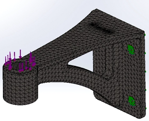
Figure 18. Mesh Created
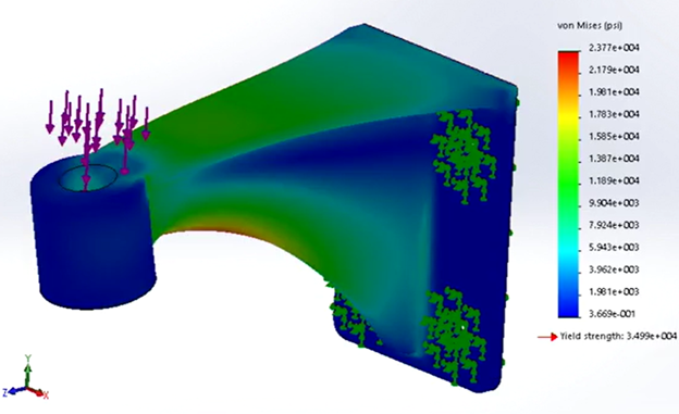
Figure 19. Simulation Run to Display Von Mises Stress Plot via Simulation Xpress
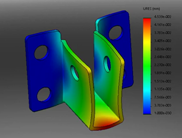
Figure 20. Displacement Plot of Second Pin
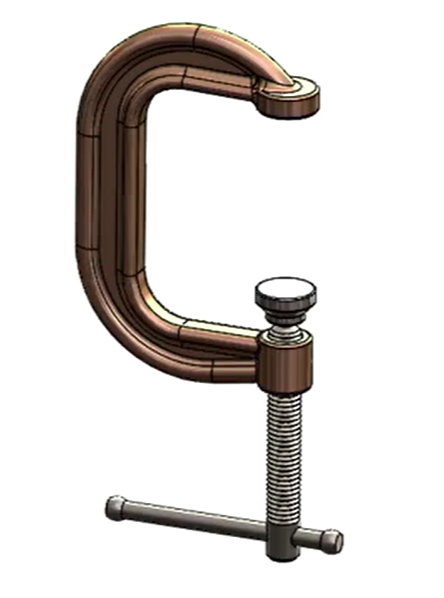
Figure 21. Design of Clamp to Study Factor of Safety
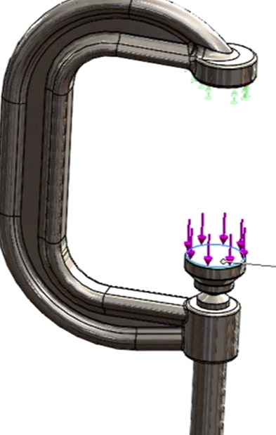
Figure 22. Load and Fixture Applications
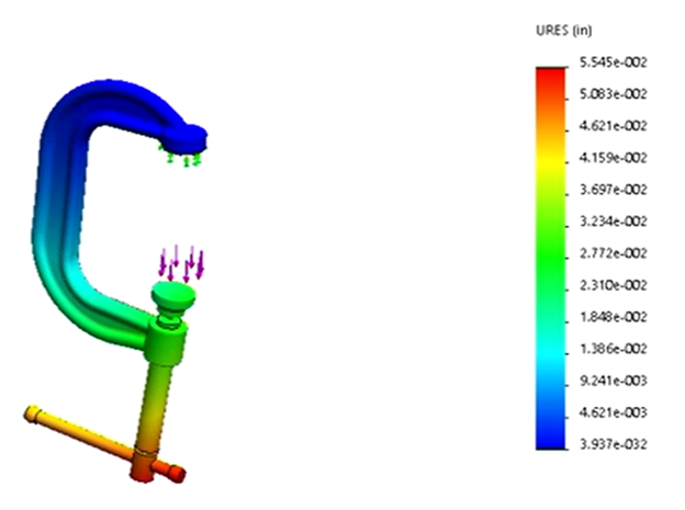
Figure 23. Displacement Plot of Clamp Simulation
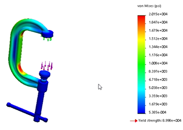
Figure 24. Von Mises Stress Plot of Clamp Simulation
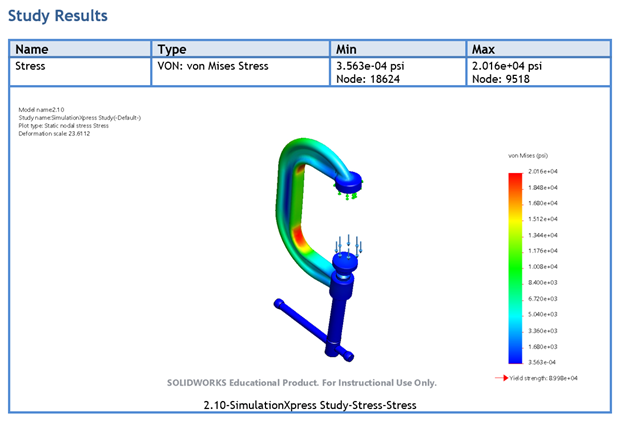
Figure 25. Generating Reports directly via SolidWorks Simulation Xpress into Word
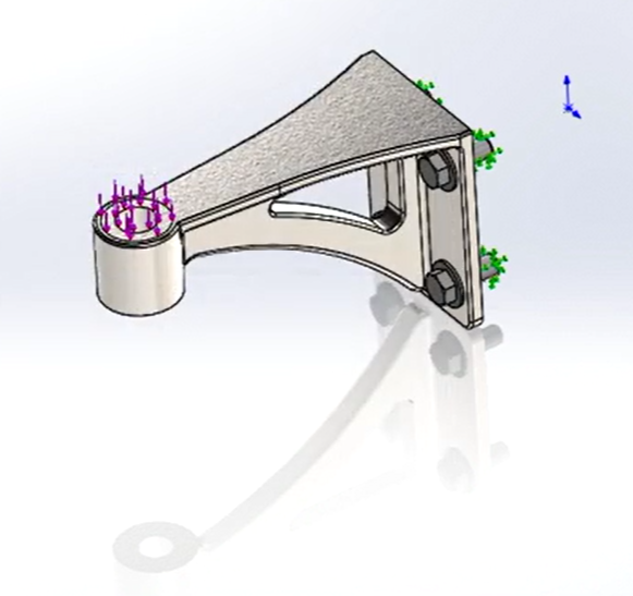
Figure 26. Fixture, Load and Material Application of Simple Assembly
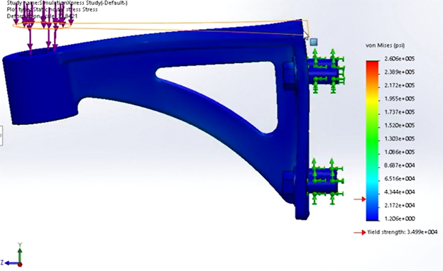
Figure 27. Simulation Result of Assembly
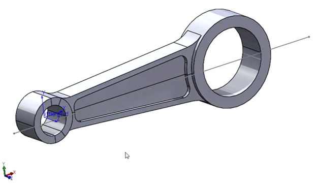
Figure 28. Design of Connecting Rod used in Piston
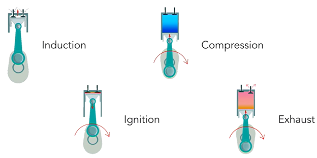
Figure 29. Power Cycle of Con Rod for Simulation Workflow
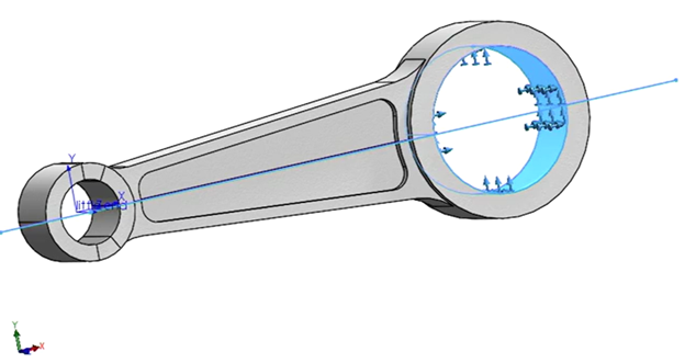
Figure 30. Constraint applied at Big End according to simulation workflow
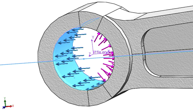
Figure 31. Combination of Tensile and Compressive Force at Little End
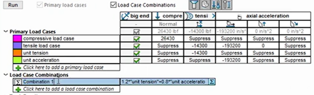
Figure 32. Created Load Case Combinations using Load Case Manager
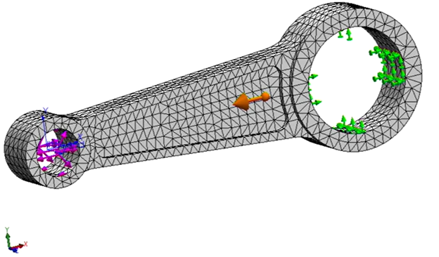
Figure 33. Preliminary Mesh Created
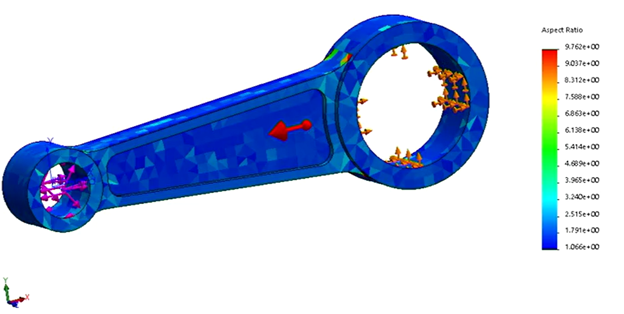
Figure 34. Quality of Mesh Inspection using Mesh Quality Plot
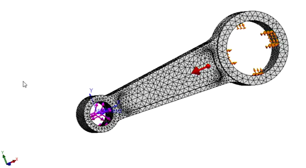
Figure 35. Mesh Adjusted to Accommodate for Curvatures
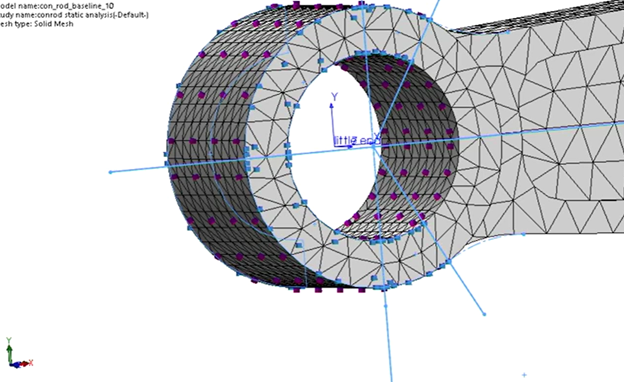
Figure 36. Adjusting Local Mesh at Little End to account for split lines and curvature
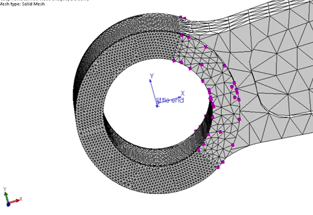
Figure 37. Adjusted Local Mesh at Little End
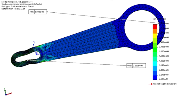
Figure 38. Analysis Result - Deformation Scaled Up by factor of 372.61
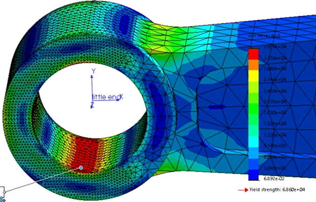
Figure 39. Stress Distribution at Little End
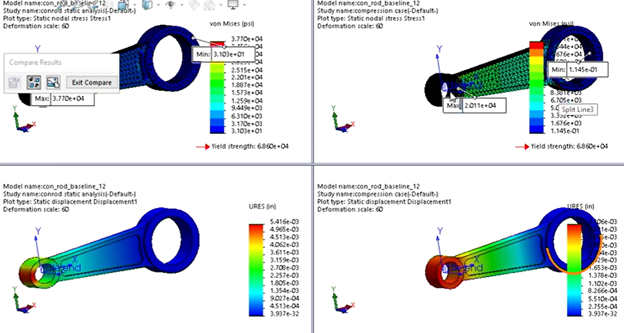
Figure 40. Analysis Comparison of Separate Load Cases
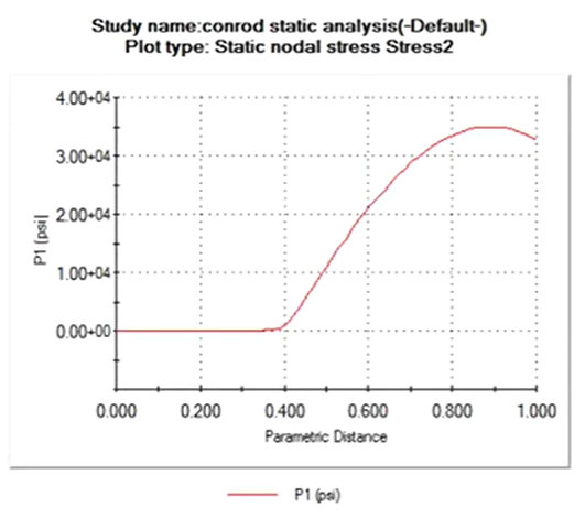
Figure 41. Stress Strain Curve Obtained from Analysis
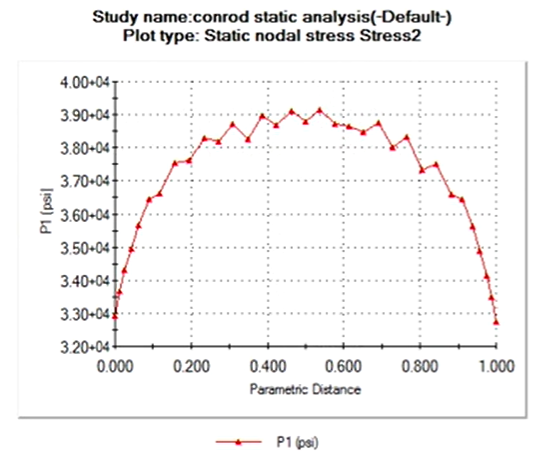
Figure 42. Stress Concentration and Distribution Plot Across a single line in the Little End
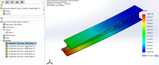
Figure 43. Dynamic Analysis Amplitude Mode 1
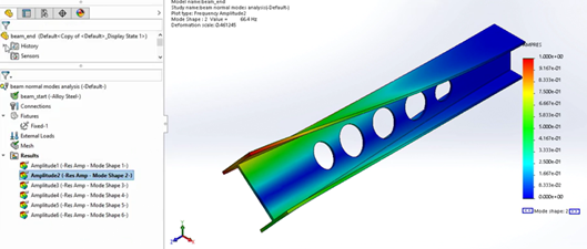
Figure 44. Dynamic Analysis Amplitude Mode 2
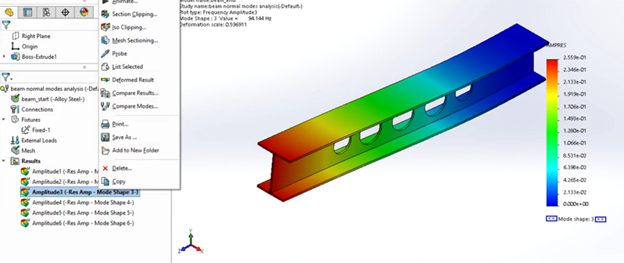
Figure 45. Dynamic Analysis Amplitude Mode 3
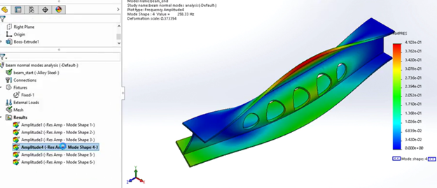
Figure 46. Dynamic Analysis Amplitude Mode 4
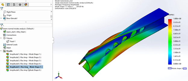
Figure 47. Dynamic Analysis Amplitude Mode 5
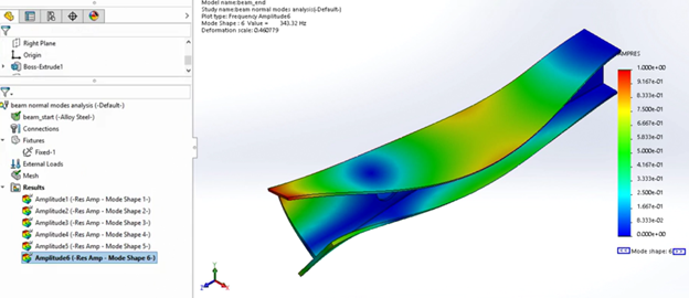
Figure 48. Dynamic Analysis Amplitude Mode 6
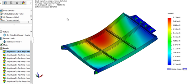
Figure 49. Distributed Mass Dynamic Analysis Mode 1/10 Result
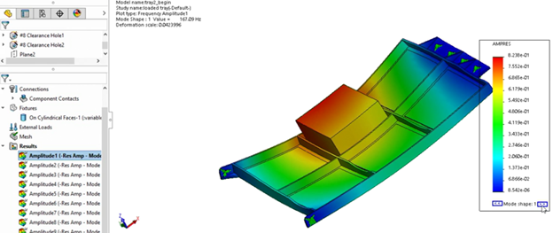
Figure 50. Payload Mass Dynamic Analysis Mode 1/10 Result
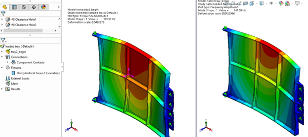
Figure 51. Lumped Mass vs Payload Mass Dynamic Analysis Mode 1/10 Result
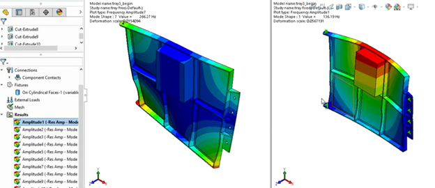
Figure 52. Non-Rigid vs. Rigid Body Dynamic Analysis Mode 1/10 Result
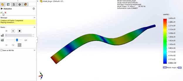
Figure 53. Centrifugal (pre-stiffened) force dynamic analysis of helicopter blade
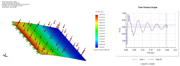
Figure 54. 6% Damping Transient Response Dynamic Analysis
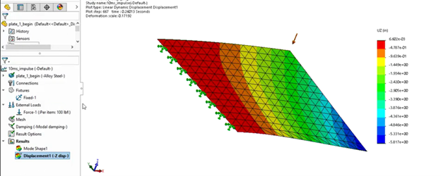
Figure 55. Transient Dynamic Analysis with Damping Effect of Simple Plate
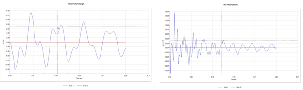
Figure 56. Displacement and Acceleration Modal Transient Response
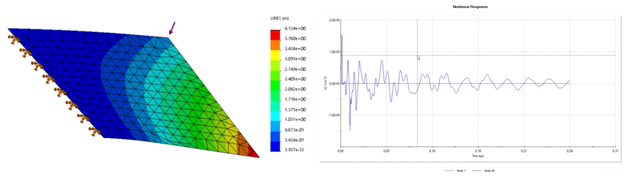
Figure 57. Displacement and Acceleration Direct Transient Response
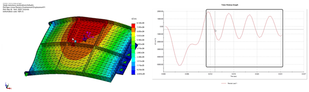
Figure 58. Base Motion Transient Analysis Response with Damping
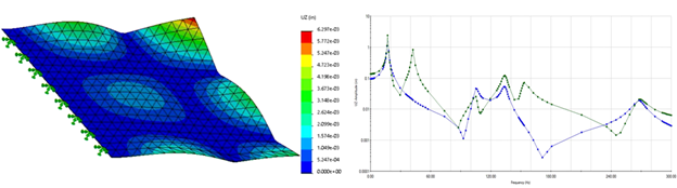
Figure 59. Frequency Response of Simple Plate under Harmonic Loading and Damping